Comparison of a 1/4 Wave Vertical for 160m vs. this design I've been playing around at. No. 1 is my design so far while No. 2 is the 1/4 wave vertical. The idea being to try to improve TX gain in a specific direction. I may actually build this or something similar to this in September this year.
Showing posts with label Inverted L. Show all posts
Showing posts with label Inverted L. Show all posts
Sunday, February 28, 2021


Sunday, February 21, 2021
MMANA-GAL - 160m Inverted L - Hightail Pitchfork
I've been putzing around with mmana-gal software - I download (for windows) this program. I have already used this to model my current 80m Inverted L with resonant radials antenna and it showed me several ways I could tweak it to tune it for R=50, Jx = 0 and a Flat SWR. If you've never built and used an Inverted L, you should recognize that as simple as this antenna looks, there is a LOT going on, and it's actually fairly complex, and VERY easy to fubar the pattern it presents, I know this first hand :-)
At any rate, I've been starting to design my new 160m Inverted L. First using resonant radials, which is probably not what I'll actually build, because of the position of the radials with respect to the wild-life, and human-life around it. (but maybe :-) I also may tweak it a bit more. I wanted to share the images from MMANA-GAL from the model I've been playing around with. This is similar to the 80m L that I'm currently using, minus the two added 'pitchfork' tines "In the front". And raised and shortened the 'trailing' radial. That's right I said, 'In the front' of the vertical antenna.
The general idea is that most of the easy DX from here is generally in EU. At least there is a high concentration of DXCC in that path. And since I'm currently sitting with 1 (USA) confirmed 160m QSL on LotW...it stands to reason that I might try to encourage my vertical to go towards EU as much as possible.
I have also been messing around with a similar model using a parasitic element (or two)...but I'm still working on that one.
Caveat: This is only the second time I've used this software to model an antenna. So I'm a newbie, and there are likely to be some oddities in what I've done here. I will say that I modeled my current 80m "L" and tweaked the model looking for a way to improve the EU directed lobe, and then tried that on EU openings every night for a week, and it was fairly obvious that the changes DID make a difference based on EU spots of my TX signal on PSKr. The predicted gain in the direction of EU showed up in my seeing more consistent deeper EU spots on PSKr. I suppose some of that could just be conditions. Since I'm also a total newbie to 80m as of just a few months ago I only had 9 confirmed worked on 80m. I'm now sitting at 91 confirmed as of today, and 118 worked.
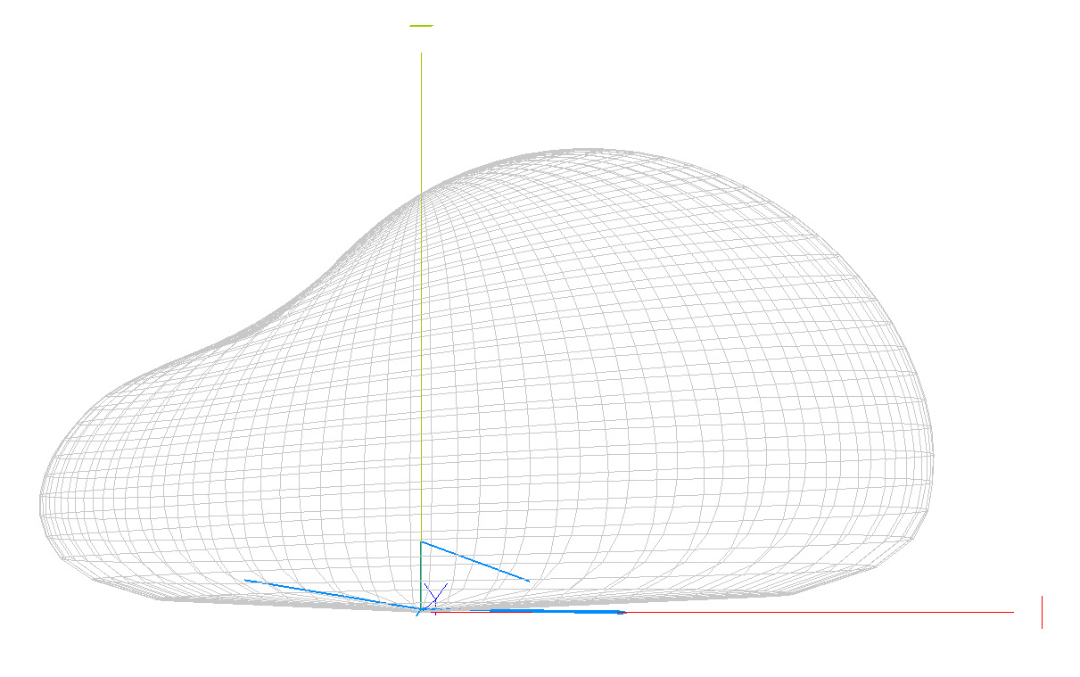
Anyway here is some of the detail of this 160m Inverted L that I'm naming an "Inverted L - Hightail Pitchfork". For the additional two "forward" radials under the horizontal "L wire" section.
The model shows a 2.0 dBi gain in the azimuth of the Horizontal "L wire" at as low as 10 degrees. And it increases from there 20 degrees shows 3.3 dBi, and 30 degrees shows 3.7 dBi. When I made similar mod's to my 80m "L" I suddenly started consistently seeing more -23, -24 spots as where I had none before. I think that's a decent indicator, although obviously it's not very scientific, but it is proof that SOMETHING improved in that path...and since I haven't changed anything else with my 200w TX setup I'm taking that as a positive indicator at the very least.
I have a LOT more learning to do. I'll admit that, and I'm a complete NOOBIE when it comes to 80m, and 160m and really anything below 30m.
Clicking on these images will bring up a larger version.


Saturday, January 30, 2021
80m Inverted "L" with resonant radial counterpoise
I've been gradually working to get on 80m and 160m.
I already built an awesomely performing Beverage Array which I'm more than pleased with. Simple to build, EASY to understand, and doesn't require a lot of precision (Love that!) So my RX is quite good on 30m down to 160m at this point. Check the RX box "OK", and move on to the TX'ing.
I've constructed an 80m Inverted "L" with resonant radial counterpoise. What a frigging pain the ass this antenna is! I thought "Oh it's just another Ground Plane with resonant radials". F'ing NOT my friends!
This antenna is a nightmare to understand, and tune. It doesn't behave like you expect if you're used to 'basic' antenna designs. At least not in my experience thus far. I don't hate the antenna. I'm just saying it's more complex than you might imagine...and almost surely will require some tuning mechanism, if the "L" was constructed properly. From what I've read it should normally exhibit 20-35 ohm. Which is likely going to present on a 50 Ohm antenna analyzer as an SWR of 2.5 - 1.4. (50 ohm / 20 ohm = 2.5 SWR, 50 ohm / 35 ohm = 1.43:1)
I think that basic math is right and the theory thereof as well.
Anyway...My radio starts to re-rate (lower) PO (power output) down to < 50w when the SWR is about 2.1:1. I am not running an AMP on HF so I just need to contend with fairly low voltages and RF watts (170w is my max output). My rigs built in ATU seems to suck in my humble opinion. It should be able to match 2.1:1 to a usable match, but it seems to be fairly useless [ Yaesu FTDX-5000]. (that's another story tho).
When I first built this Inverted L antenna I used my previous 30m Ground plane location. Which really didn't give me enough height in the vertical section of the "L" wire (the top wire). So I moved it over to where my 40m GP was located (bummer cause I was doing well on 40m) but this gave me another 10-12 feet of vertical section in the "L" wire which I think is about 32-35 feet now. The "L" wire started out at 66 feet long. The radials I used were 69 feet long initially. That combination gave me an SWR of 1.8:1 as is with no tuning. And I worked a good fat handful of new DXCC on 80m like that in a few days.
I wasn't content with that SWR. And the nightmare began!
I had been told and also read that my resonant radials should be at least 8 feet up. And then I read another very well written document saying that 10 feet would be better. The idea mostly being to reduce soil absorption. I also thought (in my own mind) that it might improve the SWR from 1.8 to raise them up. Initially I had the radials only 4-6 feet up. Very haphazardly. They are THHN wire so possibly PVC? I dunno. I have to research that a bit to find out. But it's all 14 AWG THHN wire so far. (again 66 foot "L" wire, and 69 foot radials is where I started). OK so I raised the radials up to 8 feet from feed point to ends, and that didn't really change anything.
Next I read that my resonant radial counterpoise should be 'resonant' meaning detach them from the feed point set two of them up like a dipole in their fixed position, and trim until you get the best match. I did that and ended up trimming about 5 feet off the ends (guessing I haven't remeasured it yet). That gave an SWR on the dipole "radial" configuration of 1.3:1 the best I could get. So I cut the other radials to match that length (holding them side by side - again I haven't measured them but I will). Then I reattached them to the feed point. Now my SWR wasn't good at all at 3.573 Mhz anymore. I don't remember exactly, but it was useless! The antenna seemed to want to have a nearly perfect 1:1 match at like 4.7 Mhz. So between making the vertical section longer, and the radials slightly shorter, and truly resonant things became unusable.
Because I had a hunch that the radials might be too close to earth at 8 feet up I moved them up to 10 feet. This made NO CHANGE AT ALL in SWR. I thought it might at least bump it one way or the other but it didn't.
A good friend of my loaned me two 250 pf air variable capacitors. I attached them in an L-Network and I was finally able to tune things a bit. But it still wanted to remain firmly in the 4.0+ Mhz range.
Just about to give up, I added about 20 feet to the "L" wire. And low and behold I was finally able to use the series capacitor to the "L" wire (predominantly) to tune the SWR to about 1.6:1 at the feedpoint. My MFJ-259 shows 1.7:1 at 3.573 Mhz my radio SWR meter is showing 1.5:1 and it's completely happy to TX all 170w out.
I'm still baffled by this antenna. And I'm sure I have something wrong yet.
Oh by the way I've been doing all this work through a snow storm yesterday with high temps around 20 F and lows around 7 F and gusting winds, and this morning it was about 5 F with a wind chill of -5 F while I was back out there setting up the "L" network matching setup.
Here are some pix and video of this so far. Click on the pix for larger versions.

"L" wire capacitor (250pf max)

"Ground" capacitor (also 250pf max)


1.5:1 on the radio

1.7:1 on the old ass MFJ-259
Showing R=33, X=15
"Inverted L - First tests"
Before I made any real modifications.
After significant changes. But before the final "almost resolved' fix of adding 20 feet to the "L" wire.
Current final pix as of this writing:


This still shows the "L network" capacitor to ground (the radials) but I've tested without it and there is no change.
Another variant of the "L network" that I discovered while I was trying to find where the system truly is 1.0:1 I bumped the top of the top capacitor in the photo above, while tuning the bottom capacitor, and noticed the SWR went to 1.3:1 and R=50...just by touching it with my finger between the radial(ground) and the top capacitor.
I removed the bottom cap from how I had it and instead routed it to go from the radial(ground) to the "L wire" (and the top of the top cap). Using it like this I'm able to EASILY tune 1.1:1 SWR as shown below.


Feb 2nd, 2021
Today I added a 4th radial, and I moved the "L wire" up to almost fully horizontal. Initially I thought since I was able to tune things with variable caps that I would shorten the "L wire" back to 66 ft. But I was unable to tune even with two 250pf caps as shown above.
I increased the "L wire" back to probably around 80+ feet long. And I'm able to tune it. I suspect it needs to be even longer - perhaps 88 feet something like that. I'm not able to get nearly as good a match with the 4th radial added. But I'm also aware that the more radials I add the more tuning will 'tighten up'. Meaning it will probably force me to do a better job with the "L wire".
I'm going to try these changes for a day or two and see how it behaves.


Subscribe to:
Posts (Atom)